Interpreting and making practical use of the graphical results from measuring programs like Sonarworks’ SoundID Reference or AV Nirvana’s Room EQ Wizard (REW) requires a basic understanding of acoustic physics and the way sound behaves in a room like yours. Identifying the problems that stand in the way of attaining an accurate music monitoring system is a continuous learning process that is worthwhile to pursue. There are many excellent resources (besides our site) to help you learn about acoustics that will be linked at the end of this article.
The purpose of this article is to teach you to read a room’s frequency response curve and determine the likely causes of the frequency problems revealed by the analysis. You can then improve the room’s acoustics to smooth out its frequency response before refining the sound with software like SoundID Reference. Read on to learn to decode this information that is provided by room correction software.
Room Acoustics Reviewed
Rooms used for personal studios are typically converted spare bedrooms, offices, or garages. These rooms usually measure in the range of between 2.5 m to 3.5 m (8 to 12 feet) wide by 2m to 3m (6 to 10 feet) high by 3 to 5 m (10 to 16 feet) long. Finished ceiling height in the US is typically 8 feet (2.5 m) and 2.2 m in the U.K.
The behavior of sound in a small room can be divided into low frequencies and high frequencies, based on the Schroeder Frequency. For most small rooms, the Schroeder Frequency is somewhere between 200 and 500 Hz. Below the Schroeder frequency, the entire room acts as a resonant cavity with low-frequency sound waves bouncing around creating nodes and anti-nodes. This low-frequency sound energy propagates in “waves” and is modal. Above Schroeder, higher frequency sound behaves like “rays” as if lasers are reflecting around the room.
Acousticians define a small room as a space whose acoustics are dominated by the detrimental effects of room modes that are also referred to as “standing waves” because they seem to stand still in certain locations in the room. Small rooms also have loud (higher frequency) reflections off of nearby surfaces that confuse the direct sound of the speakers. Rooms are considered large if they have dimensions over 10 meters per length, width, and height. In these spaces (like concert halls or indoor arenas) the reflectivity of the space—the reverberant field dominates the acoustics so we don’t worry about first reflections and room modes. Obviously, we all work in rooms that are considered acoustically small!
Sound waves bouncing back and forth between parallel floors, ceilings, and walls create room modes. As sound waves bounce back and forth between parallel surfaces, the waves add and cancel at various locations in the room. At some locations, a particular frequency may almost completely cancel itself out and at some locations, that same frequency may be exaggerated by several dB. Locations where cancellations occur are called nodes and locations of boosts are called anti-nodes. The exact frequencies and locations in the room where nodes and anti-nodes exist depend on the room’s physical dimensions—its length, height, and width. For bass frequencies, the walls we see may not be the same boundary that sound waves reflect off. For instance, a grid ceiling in an office is basically invisible to low frequencies, which will actually reflect off the structural ceiling above the drop ceiling.
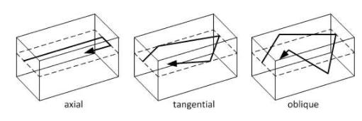
Types of Room Modes
Reflections exist not only between parallel walls but between many different combinations of wall, floor, and ceiling bounces. Different types of reflections result in three types of room modes. In every room, there are about 80 different room modes present at any given moment—but many of these modes are of very little concern.
- Axial room modes, caused by two waves traveling in opposite directions between parallel surfaces (two walls or floor and ceiling) are the strongest modes. Acousticians are most concerned with the strongest axial modes because they make up 50% of the total energy of all the modes.
- Tangential room modes are formed by waves that reflect off two sets of parallel walls (four walls or two walls, floor and ceiling). They have half of the energy of the axial modes.
- Oblique room modes involve eight traveling waves reflecting from all the boundaries in a room. Oblique room modes have only one-fourth of the energy of axial modes.
Visualizing Room Modes
If you’ve ever walked around a room while music is playing, you may have noticed that the loudness of the bass changes drastically as you walk around the room. Near the walls and corners, low frequencies are exaggerated and away from the walls, the bass may seem even or too low in level. You have physically walked among the nodes and anti-nodes caused by room modes. Once we know the measurements of a particular room, we can predict where these nodes and anti-nodes occur so that we can visualize how the bass will sound at various locations in the room and exactly what frequencies will cause trouble. This helps us define the types and locations of acoustic treatment and even our listening position. Room mode calculators are available to help us calculate and visualize these acoustic anomalies.
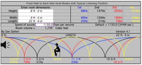
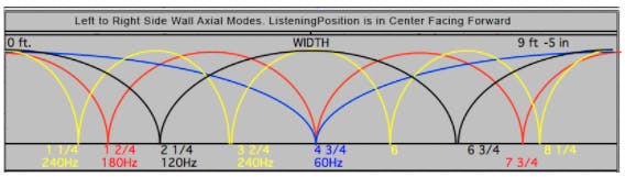
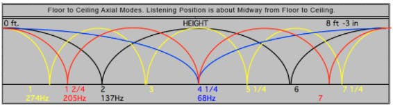
Let’s analyze a room that measures 22.4 ft (6.82 m) long X 9.4 ft (2.86 m) wide X 8.25 ft (2.5 m) high. Figures 1a, 1b, and 1c from Dan Siefert’s room mode calculator (provided by Harman) show the frequencies and relative locations of the lowest frequency nodes and anti-nodes of the 1st axial room modes. The 1st room mode is blue, the 2nd room mode black, whose frequency is two times the first, the 3rd red mode at three times the first, and the 4th yellow mode that’s four times the first.
What We Learn From This Analysis
All room modes peak at boundaries—the floor, ceiling, or walls as shown far left and right in this chart. This is the reason why when you stand near a wall or especially in the corner of a room, the pressure buildup is intense. The 1st room mode (blue) has just one node (dip) at 50% of its length dimension with the 2nd room mode (black) peaking at the same location.
Notice on each graph where any nodes or anti-nodes meet at the same location. The exact location(s) in the room where you would hear these phenomena is completely predictable and must be considered when setting up a room for critical listening. Using these room mode tools is a simple way to predict where modes will exist.
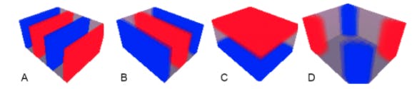
Below in Fig. 2 are some 3-D room mode visualizations created by the AMcoustics room mode calculator.
Modal Measurements in the Real World
Now that we have some theory behind us and we know how to use mode calculators to predict our room’s problems, let’s measure our room with a microphone and software to see what the real-world frequency graph tells us about our acoustic environment. We use this information to acoustically treat our room.
All the following graphs for this article were done in my studio using a Sonarworks’ calibrated measurement microphone. Some graphs were created using the free Room EQ Wizard (REW) software and some were created using Sonarworks’ SoundID Reference for Speakers software. I use Kali Audio IN-8 three-way monitors spaced 40 inches (1.02 m) apart, measured center-to-center.
This REW screenshot (fig. 3) depicts the first axial room mode dip (at 76 Hz) caused by reflections back and forth from the floor to the ceiling at the listening position. At about 152 Hz, the second room mode frequency, there is an anti-node or peak. Unless you plan to move to another room or add bass trapping, you will have to live with this floor-ceiling room mode. This problem is typical of 8 foot (2.5 m) ceilings—having a 10 or 12-foot ceiling would be a practical luxury for a home studio!
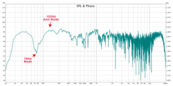
Fig. 4 below shows the SoundID Reference measurement of the same room and we see the same two aforementioned modal issues. The SoundID measurement is smoother than the REW measurement, but both measurements clearly indicate the modal problem and also Speaker Boundary Interference Responses.

Room Modes vs. Low-Frequency Reflections
Room modes, by definition, excite a room the same way that blowing over the open top of a bottle excites the bottle. Certain frequencies ring and create a resonant ringing with a long decay time. Sound that bounces off of a surface and combines with the sound from a speaker will also create dips and boosts at certain frequencies. These reflections, referred to as SBIR (Speaker Boundary Interference Responses), are worst from low frequencies reflecting from the front wall (and sometimes side walls).
Low frequencies emanate from your monitor in an omnidirectional and spherical pattern and strike all boundaries and reflect back to the speaker and of course, the rest of the room. When your monitors’ faces are 1/4 of a wavelength of a given frequency away from a boundary—like the front wall, the round trip path to and from that boundary equals a half wavelength. So there will be a cancellation at the front of the speaker cabinet—a dip at that frequency. At integer multiples of the frequency, you will have alternating reinforcements and cancellations that affect the frequency response of your very expensive studio monitors. See fig. 5.
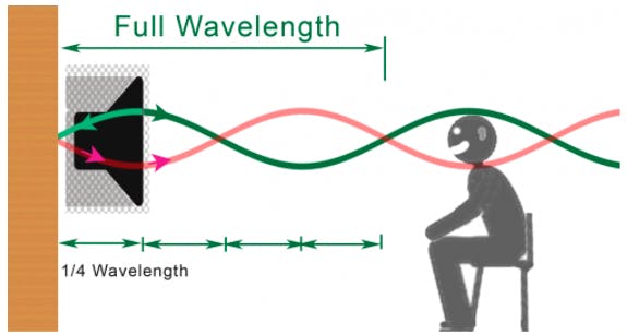
Figure 5. Here we see a low-frequency soundwave that reflects off the front wall and combines back with the original wave. At the front of the speaker and again at the listener’s head, we see the waves (high pressure and low pressure) cancel each other and cause dips in level (nodes) at that particular frequency.
Practical Considerations for Low-Frequency Problems
Keep in mind that this cancellation caused by SBIR and room modes can not be corrected with room EQ. No matter how much we boost a frequency, the room mode will always subtract an equal amount. To solve SBIR problems, speakers can be placed very close to the front wall or they can be placed two meters (5.5 feet) from the front wall. For instance, a distance of 85 cm from the front wall to the facet of your monitors will cause a node at 100 Hz, while moving the speakers to 170 cm drops the node down to 50 Hz.
Looking back at Fig. 3, the range between 300 and 800 Hz is very “choppy” with peaks and dips that are caused by the reflections from the sidewalls 90cm away and the front wall just behind the speakers about 75 cm away. I can change the location of the monitors; maybe further away from the sidewalls and closer to the front wall but there are practical limitations. Bass problems above 150 Hz can be much more easily treated with acoustic treatment than frequencies lower than 100 Hz, so moving the monitors to a location where the SBIR problems occur at higher frequencies is beneficial.
You should experiment with speaker placement in your room and measuring is the best way to determine the best compromise. I would recommend developing a routine: measure your setup with Sonarworks then make only one adjustment to your setup—such as moving the monitors further away from the sidewalls. Measure again and assess the sonic changes. Never make more than one change at a time because you might not be able to determine which changes were beneficial or detrimental.
Above the Schroeder Frequency
Fig.6 shows a waterfall graph with amplitude (y-axis), frequency (x-axis), and decay time in milliseconds (z-axis). This graph visually represents decay time and volume for all frequencies measured. Above 1kHz my small room has a fairly short and consistent decay time. This is because my room is heavily damped with broadband absorption panels—some as thick as 10 inches. At low frequencies, we see large variations in decay time and amplitude. Note the dip around 70 Hz and the long decay time around 45 Hz and 20 Hz. Long decay times will muddy up the sound. We can also see that some frequencies may be overdamped with acoustic treatment or may be reduced by reflections.

Reflections off my hard desktop and computer monitor can cause reflections and comb filtering that interfere with good stereo imaging (notice the frequency dips around 3.5 kHz). To reduce reflections, my monitors are positioned high enough on stands to look over my computer monitor and small desktop speakers. I also have my computer monitor resting directly on the desktop and tilted back at a steep angle to get out of the way of the sound coming from the monitors behind it. I’ve covered the back of the computer monitor with absorptive material to reduce reflections off of it plus my desktop surface is covered with a thin rubber shelf liner to reduce high-frequency reflections off of it to my ears at the listening position.
Why Setup Is Super Important
Your speakers’ height from the floor, the distance between them, how far away they are from the front wall, the sidewalls, and the listening position all have everything to do with maximizing how they sound in your room. An optimized setup of both the listening position and the location of your monitors is the important first step to minimize the impact of room modes. After optimizing your setup, measure the room to define how to effectively deploy acoustic treatment, (bass traps, absorption panels, and diffusers) in your room.
After setup and acoustic treatments are optimized, then run Sonarworks SoundID to get that last 10% of acoustic perfection. When your room acoustics are dialed in, Sonarworks doesn’t have to work as hard to get your room to sound super!
Programs like Room EQ Wizard (REW) measure how your speakers sound in your room from a single listening position. SoundID Reference expands on this idea and measures the sound from many points around the listening position to obtain more information about the listening space, which helps create an effective sweet spot that sounds even and accurate.
The goal with Reference 4 and the latest version SoundID Reference from Sonarworks is to measure and correct your monitors as they reproduce sound in your room. Factory speaker specifications are measured in anechoic chambers where there are no detrimental room acoustics. Many monitors boast a flat frequency response, but none of them will produce exactly that response in a small, untreated room. Understanding how your room and speakers interact and how to predict, measure, and treat the acoustic effects of your room will allow you to get the best sound out of whichever monitors you choose to use.
More information on these topics:
Should You Place Your Speakers Against the Front Wall (all about SBIR)


