By now, you are all familiar with the idea of parallel processing in mixing, but have you ever heard of parallel recording? In this article Barry Rudolph explains the benefits of parallel recording and how to effectively accomplish it. For those DIY-ers out there, at the end of the article, Barry includes plans to build your own high-quality passive microphone splitter. – ed.
The particular choice of microphone, positioning and, of course, the musical performances made in front of it constitute the “source” for the microphone preamplifier. The microphone preamp is the most crucial part of the recording chain; it can either assure the faithful conversion of the source and all its subtleties or add a colorful flavoring or a mix of both. (See this article for more info about preamps.)
I have reviewed many microphone preamplifiers (many of my reviews are available here) and I have tried to catalog the most important subjective factors that determine what I would like to have in a good microphone preamp. I found that the fairest way to test a new preamp would be to compare and contrast it to a known preamp—one you already own or is in the channel strip of your studio’s console.
I compare microphone preamps in real-world recording sessions where they show their true versatility. Using a microphone splitter, I record the source using my preferred mic choice positioned in my usual way simultaneously through both my favorite preamp and the review preamp (the one under test). After the session with the two preamps recorded to separate tracks, I can playback and evaluate the two recordings in a more relaxed setting.
Carefully “splitting” the microphone’s signal with a proper splitter allows it to be equally distributed to as many as four preamps all at the same time. The source, microphone, and mic positioning are identical so any differences in the sound are directly attributed to the preamp itself.
Performing many preamplifier shootouts led me to build a proper, high-quality microphone splitter using Jensen Transformer’s JT-MB-E Microphone Bridging Transformer and Jensen’s circuit suggestion.
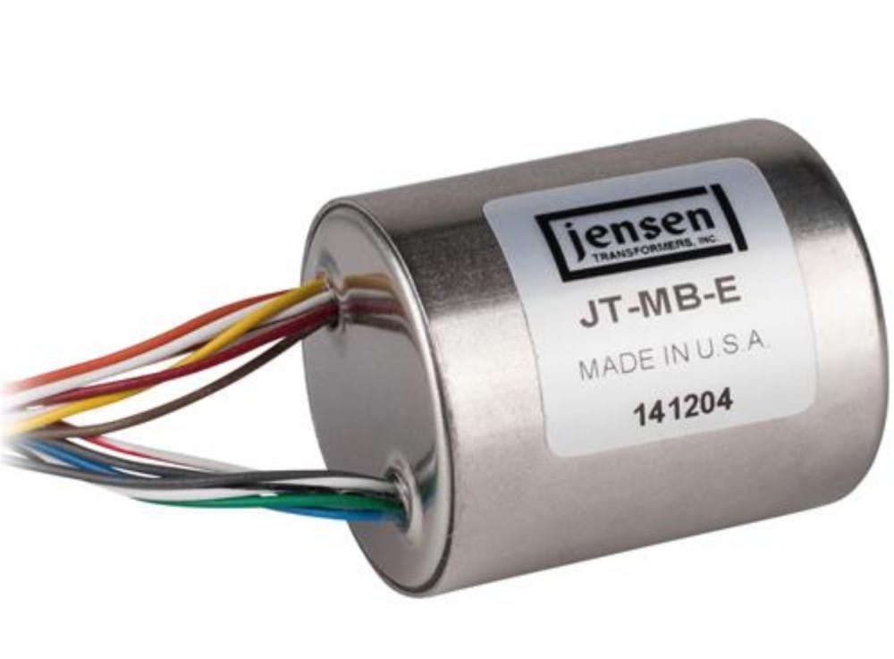
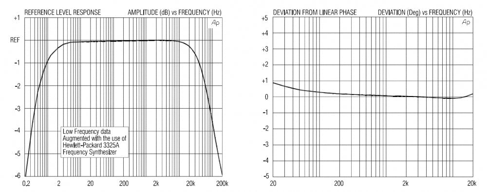
Pictured above: JT-MB-E 4-way microphone splitter transformer. Below: The extremely flat frequency and phase response of this transformer speak to its suitability for critical mic splitting duties. More details, including a full schematic diagram for the splitter, can be found below, in the DIY section of this article.
Benefits of Mic Splitting
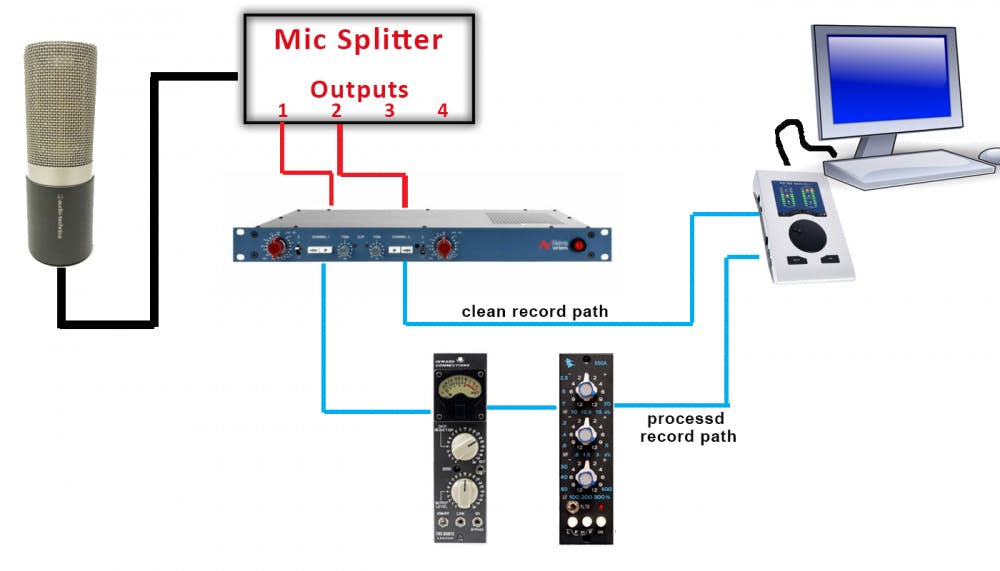
Besides testing purposes, I usually like to record a single microphone processed through two different chains. This can easily be accomplished on a recording console but is more difficult to do accurately with most “all-in-one” DAW interfaces.
I call it “Parallel Recording” where one chain goes straight from a preamp into the DAW without any processing and a second chain might have an EQ and compressor after the preamp. I would use either two identical microphone preamps or two channels on the same console, or I can use two completely different mic preamps; tube and solid-state models. Each preamp output goes to its own track in the DAW.
This is a worthwhile exercise for picking a microphone to use for lead vocals; you’ll discover certain mic/preamp combinations work better for soft singing than for loud or for male or female singers. I’ve used one microphone and processing chain for verses and another chain for chorus vocals or for doubles. With a mic splitter, you can have all of this setup and “dialed in” ahead of time.
A second advantage of using parallel recording is that one channel can be set so that it will never overload, no matter how loud the singer gets. If one channel sounds great on the soft parts of the song but overloads on the loud parts, the second channel will safely capture the loud parts. This “safety track” can save your butt if a singer (or voiceover actor) has a magical performance that overloads your main channel. Try setting one channel to your normal gain setting and the second mic pre at least 10dB lower. You could also simply apply the input pad to the second channel at the same gain setting as the first channel.
Some preamps, including the Manley Dual Mono, Avalon 2022, and Phoenix DRS2 provide two outputs from each preamp channel. Some preamps provide a transformer balanced out and a simultaneous transformerless out, while some preamps provide balanced and unbalanced outputs simultaneously. However, splitting the mic before the mic preamp provides even more amplification and processing options.
Achieving the Split
Splitting a microphone signal is a delicate process. Microphone signals are extremely low-level signals that must be treated carefully or the signal will become distorted, noisy, or otherwise colored. Don’t be tempted to simply use a “Y” cable to send the output of a microphone to more than one mic preamp. This wiring can cause phantom power problems as well as strange microphone behavior due to loading the microphone with too low an input impedance.
Microphone splitting transformers have been around for a long time. We often use splitters in live sound to split the stage mics’ signals into three (or more) separate feeds or “splits”. One feed is for the front-of-house mixer’s console, a second goes to the monitor mixer’s console and a third might go to a live recording or broadcast system. All of these systems get the same, but isolated, microphone signal to be used as each engineer sees fit for the job at hand.
A microphone splitter also has to provide galvanic isolation1 and the ability to float or lift the ground connection to pin 1 of the XLR output connector. In a live show, the FOH console’s ground and the stage equipment’s ground might have a (potential) voltage difference. This voltage difference can cause ground loop buzzing or even be an electrocution hazard (so be careful!!). Transformer-based microphone splitters solve the problem of this ground difference to provide quiet and safe splits.
In my “Transformers: Magically Colorize Your Sound“ article, I explain the inherent properties of certain vintage transformers that add to or change the sound quality favorably. With transformer mic splitters the goal is for the transformer to be as sonically transparent as possible. Apart from a little insertion loss2, a good splitter transformer will have excellent frequency and phase response plus good noise and RF3 interference rejection.
The Microphone Bridging Transformer
A bridging or splitting transformer is a very carefully made transformer that can be expensive. It has a primary winding for the input signal from the microphone and then multiple secondary windings. Each secondary winding provides an identical and isolated balanced output with the typical microphone output impedance of 150-ohms; it’s designed to be loaded by the 1K-ohm input impedance which is typical for microphone preamps. Ideally, every output of the splitter will produce the same signal level and source impedance so as to appear to the microphone preamps as just like a connected microphone.
The Jensen JT-MB-E Microphone Bridging Transformer excels with only 2.2dB of insertion loss, which is easily made up by the mic preamps. There are four separate windings (one primary and three secondary windings) with Faraday shields4 for each winding with up to 30dB of magnetic shielding by way of its mu-metal5 housing.
The Jensen JT-MB-E has three isolated balanced outputs and a “Thru” output for the input microphone counting as the fourth output. Besides establishing the ground reference, this first thru output will pick up the +48-volt phantom power from preamp #1 for the microphone if required. With a splitter box based on this transformer, you can have up to four preamps (or recording consoles) fed from one microphone.
Jensen Transformer also makes the JT-MB-D Microphone Bridging Transformer with two isolated balanced outputs. It has less insertion loss at 1.2dB and also costs about 30% less. It is the same quality and if you elect to use this transformer in this splitter box, you can have up to three preamps fed from one microphone.
The Jensen JT-MB-E schematic (see the DIY section below) shows individual ground lift switches for each of the three outputs and each output has its own RF filter network. The braided shields in all mic cables can act as antennas and pick up nearby radio energy—cellphones, two-way, WIFI, stage walkie-talkies, wireless microphones, etc. This energy will impose itself on the microphone signal and generate noise in the audio signal. Even with the ground lifted, these RF filters always terminate6 the connected mic cables’ shields to ground above 300-kHz and eliminate radio frequency interference without affecting the audio signals.
Many companies sell passive microphone splitters, though few of them have specifications as good as Jensen Transformers. Electronic mic splitters may provide additional features, such as built-in phantom power, pads, gain matching, or filters, but the audio quality (purity) will certainly not match a good passive transformer split. My solution was to build my own box for under $200 in parts and a few hours of assembly.
Below are the instructions on building your own Jensen Transformer mic splitter. For those who prefer ready-made options, here are some off-the-shelf mic splitters, listed in order of cost from highest to lowest:
Radial JS3 1×3 Microphone Splitter (with Jensen transformer)
Radial Pro MS2 1×3 Microphone Splitter (with Eclipse transformer)
Switchcraft RMAS1 1X3 Microphone Splitter (also available as 8 input with 3-way split)
Whirlwind IMP Microphone Splitter 1×2
The Jensen Transformer Mic Splitter Transformer Box DIY
Instructions and notes for building the mic splitter using the JT-MB-E
- All schematics and application notes included in the download are courtesy of Dave Hill, general manager of Jensen Transformers at 9304 Deering Ave, Chatsworth, CA, USA 91311 (818) 374-5857
- The transformer in this project may be purchased directly from Jensen Transformers. Contact info@jensen-transformers.com phone: +1 (818) 374-5857
- All the information, parts list, schematics, and images are downloadable at: https://www.barryrudolph.com/jensen_mic_splitter.zip
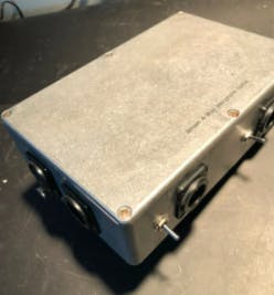
The image above shows the finished splitter box. I used the same die-cast aluminum Hammond box for most of my DIY projects. But the splitter transformer is much smaller so you could use a smaller box if you like. I find that this size fits almost anywhere in the studio or on the road and is rugged enough you can put it on the floor out of the way.
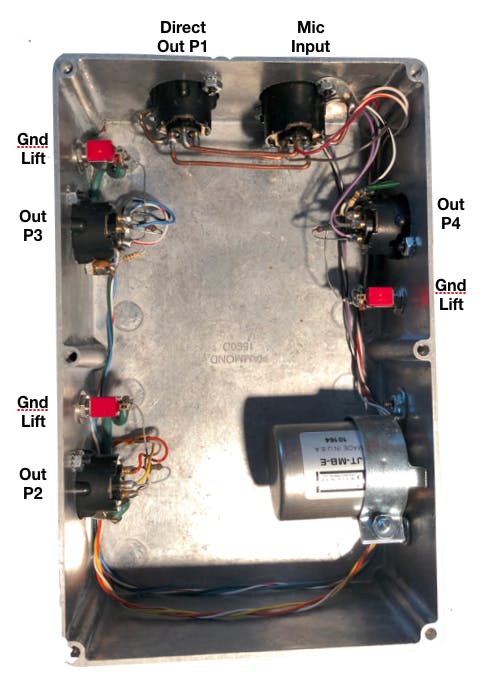
This image shows the same box with the cover removed. In the lower right is the Jensen JT-MBE Transformer firmly mounted on the inside wall of the box. You can see the many different colored-coded wire leads coming out of the transformer’s base.
It is important to build this box well using good hardware and locknuts with star washers that “bite” into the aluminum case to make a good electrical connection. The metal case acts as an overall shield against external intrusive electrical noise. Microphone signals are very low level and susceptible to noise.
The labels around the box match the Jensen schematic nomenclature in the documentation.
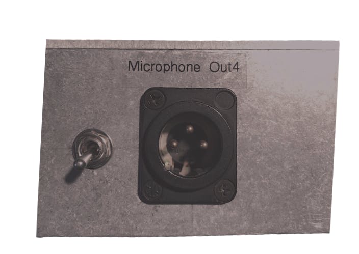
This image shows the ground lift switch that is available on outputs 2, 3, and 4. The wiring details and more photos are included in the downloadable project details.
Build Notes:
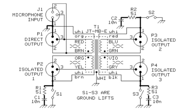
It’s super important to make sure that the “•” mark on the transformer’s schematic always goes to pin 2 of the XLRs. This keeps the microphone polarity the same for all outputs.
I used #14 solid copper bus wire to parallel J1 and P1 and provide a good soldering point for the red and brown primary winding wires. See image6.jpg in the download.
The wiring job around the XLR output connectors is not pretty. This is because you need to keep the leads for the ground wire, the 51-ohm resistor, and the 10nF ceramic capacitor of the RF filter as short as possible. In Image 2, you can see the three, red-colored miniature ground lift toggle switches. You can use any SPST switch you like. It is not critical at all but just keep the wires short.
See Page 3 of the Jensen Application Notes in the download for the technical explanation and much more about the requirements of a proper mic splitter.
Below is the wiring schematic for the 4-way transformer split suggested by Jensen Transformers. This and more details are included in the download.
Vocabulary Used In This Article
1-Galvanic Isolation
Two or more circuits separated both electrically and physically so as to block stray currents such as differences in their paths to ground and extraneous noise induced by outside sources.
2-Insertion Loss
The inherent reduction of level due to the inefficiencies of the device itself or the system’s design.
3-RF
Radio Frequency interference—noise from nearby radio sources such as WIFI, cell phones, Bluetooth, AM and FM radio stations, electronic light dimmers, and cheap wall-wart power supplies, and much more!
4-Faraday Shield
A Faraday shield or cage (named after Michael Faraday who invented it in 1836) is made from a continuous sheet of conductive material or screen mesh. All four of the coil windings in the Jensen JT-MB-E Transformer have separate shields to block the intrusion and interference of radio frequencies from external sources.
5-Mu-Metal or mu-metal
Mu-metal is a nickel-iron soft (completely malleable) ferromagnetic alloy with very high permeability. Permeability is the resistance to the formation of magnetic fields. Mu-metal is used for shielding a transformer from radiating stray magnetic fields to nearby sensitive electronic equipment. Magnetic permeability is represented by the Greek letter mu.
6-Terminate
Any stray signals and noise are easily carried on high impedance lines (such as an electric guitar cord) and to prevent them from traveling any farther into the attached microphone preamps, the RF filter terminates or “kills” it by shorting it to ground—the splitter’s aluminum case is ground.


